WALTER SPIERINGS
Dutch Holographic Laboratory BV
Eindhoven, Los Paises Bajos
P.P.Q.M. SOONS
Volcan, Panama
RESUME:
-We describe the process how to reconstruct the 3D data in the image in the Shroud of Turin with Holography.
-Copies of the negatives of Giuseppe Enrie of 1931 are digitized and enlarged to improve the details.
-The gray levels in the Shroud data were then translated into depth data.
-A sequence of up to 625 images was generated and these were combined with our Holoprinter into a 3D image of the Shroud.
Introduction:
In 1977 John Jackson and Eric Jumper analyzed photographs of the Shroud. In their experiments they used a microdensitometer to follow the ridge lines to obtain a graphic record of the relationship of the image intensity of the cloth-to-body distance. They were able to conclude that Vignon’s hypothesis (that the image on the Shroud varies inversely with the cloth-to-body distance) was correct. They then subjected the image points of the Shroud photos to VP-8 image analysis One of their findings was that their process resulted in an anatomically perfect 3D model.
Since then more 2D to 3D conversion processes have been described (Tamburelli, Balossino).
In our initial tests we used a commercial available tool. From the Shroud data we extracted a gray scale height image and used this to generate a 3D image of the Shroud.
We made several views of this 3D model and we generated an anaglyph image which made viewing in 3d possible using red and cyan glasses.
This convinced us to continue, and more sophisticated methods were developed.
A virtual camera moves in a horizontal line past the 3D model. Between the center view and the most left and right image all the other images (623) are interpolated.
These sequences are used in the DFCH Holoprinter developed at the Dutch Holographic Laboratory in Eindhoven, the Netherlands.
For the large size holograms (100×50 cm and 200×100 cm) we chose the one step process, because it is an easier possibility to produce large size holograms.
Holography process
Theory:
The theory which we have developed (1,2) is different to the existing theories. We compare making a Computer Generated Hologram (CGH) or a Multiple Photo Generated Hologram (MGPH) with making a Traditional Hologram (TH) of the same object. Because in the end we want the CGH to look the same as a Traditional Hologram (TH) of that original object.
By using a reversed reasoning we were able to develop this theory.
The theory describes the exact recording geometries. Of course this way of recording is in itself astigmatic.
The vertical parallax doesn’t change. The horizontal parallax does. Using a long enough H1-H2 distance takes care of this problem and the astigmatic effect is not noticeable.
We will summarize this theory (MPGH) see also.
Theoretical principle of geometrical method for artificial holography
To perceive true perspective in an artificial hologram we made an analogy with a traditional hologram of an object. When this hologram is illuminated with its conjugated reference beam the recorded object focuses 3D in space.
If we slit a hologram, by cutting the hologram up, we could join these slits together and we would have of courses the same hologram. Of course, if the slits are not adjacent to each other but a little apart the object would become distorted. Imagine we reconstructed the hologram of the object with the conjugate wave. If we only illuminate a small dot of the hologram the object will be reconstructed. It doesn’t focus in space though and we can project this image on a screen at any distance. A dot adjacent to the first dot will give a flat slightly different perspective of the object.
Is it then possible to reverse this process, to make a 3D hologram using only 2D images (without the vertical parallax)?
Therefore we divided the hologram in 150 dots on a horizontal line. Instead of projecting the images produced by every dot on a screen, we use photographic paper instead. If we holograph every picture that is on the photographic paper in the right dot, we could record the same hologram as before and we reversed the process.
Instead of using photographic paper we can make slides of the real object at the position of the different slits and project these on a transparent screen. The slides have to be taken in such a way that the projection of these slides will give the same result on the screen as the photographic paper did. So how can we determine how to take the right perspectives and what parameters and involved?
The new approach:
We use the analogy with a traditional hologram as explained before.
We will look at two methods.
1) We can make pictures of a real 3D object.
2) We have a 3D object in a computer and a software camera makes the slides. The slides are then visualized on the computer screen. To transfer these pictures to the holographic setup we make photos of the screen (1:1)
Alternatively we use a LCD screen in the setup.
We use the set-up proposed by King de Bittelo, Benton, Newswanger, Molteni.
The Recording:
First we discuss the recording of an object point and show that the 3D location is transferred to a deviation on the slide, relative to a previous slide in the sequence. This deviation is the only depth cue during the process and describes the 3D object. We will define this deviation during the conversion process of object till hologram.
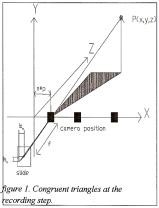
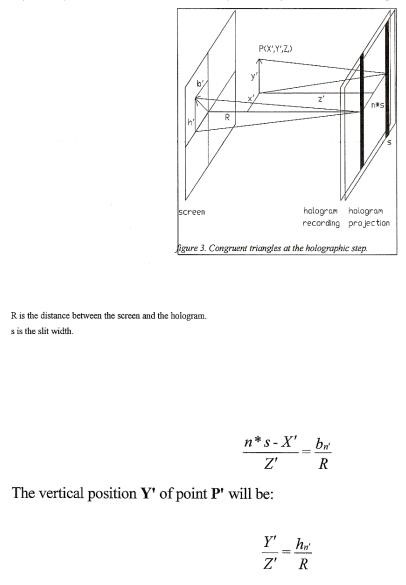
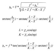
A point P (X,Y,Z) in space will be focused on the slide at a point P (b,h) the center of the slide is the origin, see fig.1.
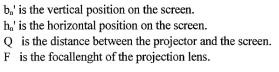
The relations between these two points are

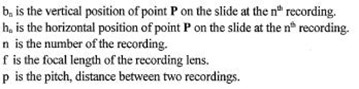
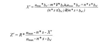
When the slides are projected on the screen (see fig 2.) the pictures will be rescaled by a certain factor according to:
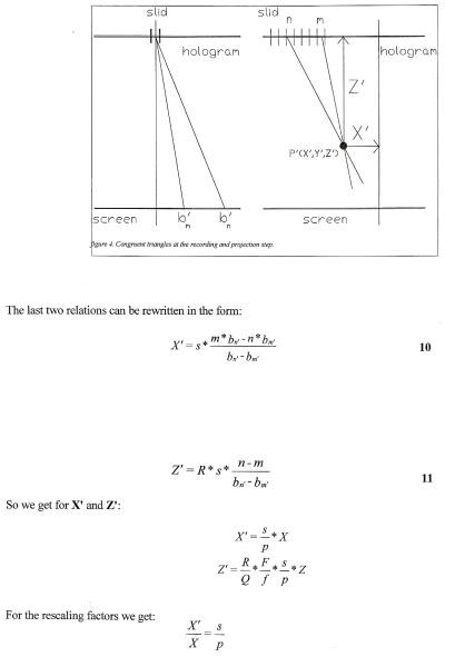
As explained before all slides will sequentially be recorded on the right slits. The point we recorded P (X,Y,Z) will focus at locations P (X,Y,Z) behind the hologram. See fig. 3.
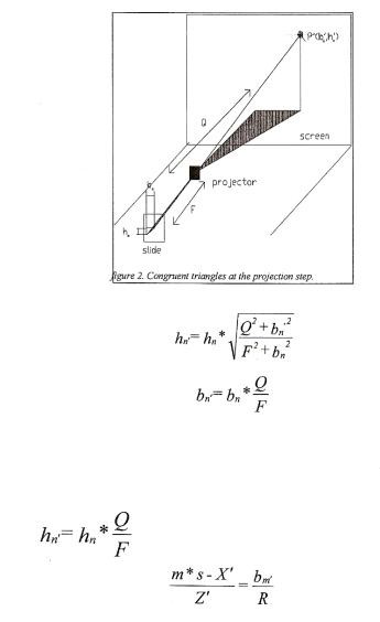
In the first section we have presented the calculations concerning a recording on a straight track, perpendicular to the subject. Now we discuss the geometry and calculations for a circular track recording. In the first case the holographic plate was moving and the slit was on the optical axis. Now the holographic plate has to be fixed and the slit will be moving. The geometry is as shown in figure 5:
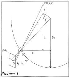
All the parameters are the same, except for the pitch that now is a given in rad (p rad)
From figure 5 we can derive the next equations by congruent triangles:
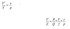
As we have seen before, the point (P ba, Ba) will be rescaled on the screen by a factor Q/F. With the projection of the hologram, the original point P (X,Y,Z) will result in the point P (X,Y,Z) that can be calculated as follows:
We have written an interactive computer program to calculate the right geometry for an undistorted MPGH.
LCD Experiments:
The long term goal is to let the computer address a printer after which the hologram is printed. Obviously we need an electronic display interface between the CAD system and the hologram printer, to be able to address the printer directly. Therefore the Dutch Holographic Laboratory has approached Philips Corporation for assistance in the interface between the computer screen and the holographic projection screen, by using a very high resolution LCD screen. This would of course result in a perfect registration of the different views.
The LCD screen used was a black and white active matrix type measuring 6 inch diagonal. Because we polarize laser light we did not use the entrance polarizer increasing the transmittance by 20% to 40% (immediately behind the screen we placed a diffuser). Resolution of the screen was 1024 pixel by 768 pixels. The test hologram made: shows that holograms using this screen have at least the same resolution as holograms made using slides shot from a 20 inch CAD work-station monitor. Currently we have upgraded to LcoS display chips which increases the resolution to 1920×1200 pixels. This eliminates any visual pixilation in the hologram.
Conclusion:
We have proved that it is possible to produce 3D holograms from suitable 2D data. We used a digital 2D to 3D conversion process. With these data we showed, that it is possible to produce a convincing 3D image.
We have shown that making undistorted MPGH does not follow the rules and tricks of stereo pairs and stereo windows. Because of our approach of comparing the MPGH with a normal hologram of the object, the position of the viewer is not important for this method.
We successfully tested a high resolution LCD screen and LcoS chip as a digital interface between computer data and the holoprinter setup.

Holoprinter

Holoprinter

Holoprinter

Click to see article HOLOPRINTER INFO DHL WALTER SPIERINGS
Click to see article ILUMINATION HOLOGRAMS